
Designing, Fabricating, and Coding An Automated Greenhouse
The experience of burying a seed and seeing it grow into a produce-yielding plant has always appealed to me. However, six months ago, I realized that I am actually terrible at keeping plants alive. While my poor watering habits are mostly to blame, the indoor environment that housed my plants also negatively impacted their growth. For context, this was during the winter months. Despite being inside, I could tell that the low light, temperature, and humidity were severely stunting the growth of my plants. This spurred me to make a greenhouse that could autonomously water, boost photosynthesis, and monitor/correct temperature and humidity levels. And so, six months later, this is what I came up with.


I feel like I often say this, but man, did I underestimate how difficult this was going to be. For starters, it doesn’t have all the features I originally intend, yet. That said, it still does a great job keeping plants healthy and growing, so I’d call it an in-progress success. So here’s how it works.
Enclosure
Starting with the enclosure, I decided to use 1/8” clear acrylic sheets, which I cut out using a table saw for the panel outlines and a laser cutter for the smaller details. To attach the panels, I used Weld-On 3 acrylic cement. I strongly recommend using this adhesive for acrylic-based projects due to its extreme strength and easy application. It also doesn’t cloud or damage the acrylic’s finish like other glues. In addition to using Weld-On, I also lined the water reservoir with clear silicon to reduce the chance of leaking (It still leaked). For version 2, I also added a magnetic access panel to easily adjust the misting nozzles while still keeping the humid air in.

Figure 1: V1 AC submersible water pump test
Figure 2: V2 misting nozzle test
Watering System
Surprisingly, the watering system was the trickiest of this project to get right. My goal was to create a system that could evenly distribute water while also atomizing it enough to increase the average humidity of the greenhouse. Initially (V1), I used an AC submersible water pump, similar to this one, which is typically used in aquariums. While they effectively move large quantities of water, I found these types of pumps don’t generate a significant amount of pressure. The pumped water flowed into the soil through a bent acrylic tube, exiting through evenly spaced .055” diameter holes. As you can see from figure 1, this method failed to distribute water evenly and had little effect on the greenhouse’s overall humidity.
For V2, I swapped out the submersible pump for this 12V diaphragm pump which is rated at 110 PSI. I also swapped out the acrylic tube for the misting nozzles found in this Irrigation kit. As seen in figure 2, this combination worked beautifully. It was also at this point I added the adjustable nozzle arms and magnetic access panel. The adjustable arm mount can support up to six arms, but the habanero plant I’m currently growing only needs two sprayers. I also needed to upgrade the electrical system when I switched pumps—more on that in the next section.
Electronics system
Most of the electronics, excluding the temp/humidity sensor and the photoresistor, are mounted to a 5”x10” acrylic sheet located next to the greenhouse. The diagram, seen in Figure 3, outlines these various components. Starting at the top, there are five JST headers. This is where the cables from the greenhouse connect. Moving down, there are two L298N dual h-bridge drivers. The driver on the right powers the twin fans mounted to the enclosure. It can also vary each fans’ RPM using a PWM signal from the microcontroller. The pump driver on the left functions similarly, with the only difference being that both h-bridges of the L298N drive the pump. This is to spread the 3A current draw of the pump out evenly on the driver. Below that is the microcontroller. I'm using an Arduino Nano for this version, which has more than enough power/memory to run the needed code. The Nano is responsible for:
controlling both fans independently
watering frequency and amount of water dispensed
switching the LED panel on/off depending on the time of day
monitoring the photoresistor to determine when ambient outdoor light crosses the set day/night threshold
To maintain an ideal growing environment, I eventually want to integrate PID systems to control temperature and humidity. I also want to add a user interface that allows the user to monitor/configure the desired temperature & humidity. I’ll probably need something more powerful than a Nano at that point.
Moving forward, the next component in the diagram is the fan speed potentiometer. This pot sends an analog signal to the microcontroller, which turns it into a PWM signal sent to the fan driver. Pretty straightforward. Next to that is the LED relay switch. This switch, which the Nano controls, connects/disconnects the high-voltage power from the LED panel driver to the LED panel. The LED panel driver, located below, converts AC power into 36VDC, which drives the LED panel. Moving down is the AC to DC converter, which supplies the entire system, excluding the LED panel driver, with 12VDC. The last component, which is not shown in this diagram, is the photoresistor. This light sensor measures the ambient outdoor light and sends it to the Nano. The Nano uses this data to determine if it is currently day or night. The photoresistor is mounted to the inside of the nearest window using opaque tape, which isolates it from ambient light inside.
See the list below for links to all of the hardware I used:
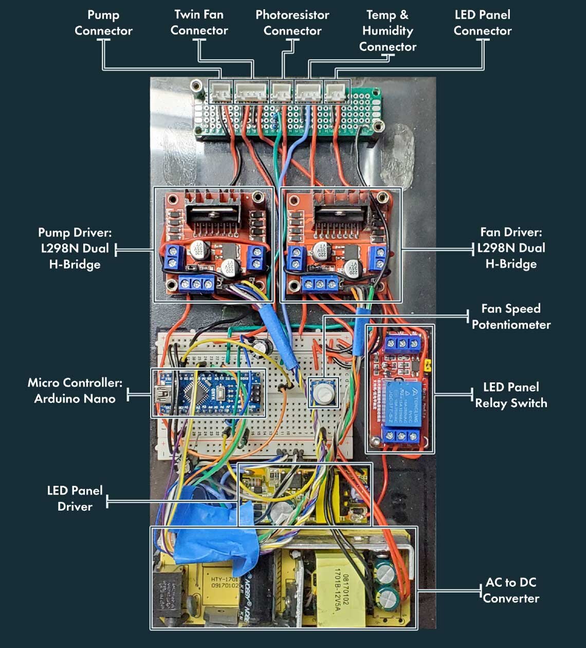
Figure 3: Electronics hardware layout diagram
Code
The following code gets uploaded to the Arduino Nano. I’m not going to get into too much detail about it, but I will outline some of the key configurables and one of the major bugs I’ve noticed after using it for about 2 months. The following lists the key variables and what they do:
“int LiteThres” This value determines the reading needed from the photoresistor to trigger a switch in the day/night cycle counter. Ideally, this value is set to the amount of light measured during dusk or dawn.
“int pumpPWMlimit” This value controls the amount of voltage sent to the pump and will be different depending on the pump used.
“long intervalPump” Determines how long the pump will run when a watering cycle is triggered. In other words, the amount of water dispensed.
“int pumpCycles” This determines the number day/night cycles needed to trigger a watering cycle.
There a couple of other things you may want to change, but these are the most critical. As for that major issue, there’s currently no debounce timer on the day/night cycle counter. As a result, occasionally the photoresistor will oscillate above and below the light threshold, triggering multiple waterings despite only one actual day/night cycle taking place. It’s an easy fix, but I just haven’t had the time or patience for it yet. I’ll be sure to update this article when I do.
#include <Adafruit_Sensor.h>
#include <DHT.h>
#include <DHT_U.h>
/**
* Pinout:
* D2: Pump Relay (ORG)
* D3: LED Panel Relay (YEL)
* D4: Humidity Sensor (RED)
* D5: Fan Top (GRN)
* D6: Fan Bottom (BLU)
*
*/
#define OnBoardLED 13
#define Pump 6
#define fanPWRpot A7
#define LEDP 2
#define DHTPIN 10
#define FanTop 3
#define FanBot 5
#define LiteSens A0
#define DHTTYPE DHT22
DHT_Unified dht(DHTPIN, DHTTYPE);
int PumpState = LOW;
int LEDPState = LOW;
int FanTopState = 100;
int FanBotState = 100;
int FanPWRread;
int FanPWR;
long previousMillisPump = 0;
long intervalPump = 100000;
long previousMillisLitesens = 0;
long intervalLitesens = 50000;
bool currentLEDPState = 0;
bool previousLEDPState = 0;
int previousDNcycles = 0;
int currentDNcycles = 0;
int pumpCycles = 1;
int pumpPWMlimit = 200;
int LiteThres = 350;
const int numReadings = 90;
long readings[numReadings]; // the readings from the analog input
long readIndex = 0; // the index of the current reading
long total = 0; // the running total
int LiteAverage = 0; // the average
void setup() {
Serial.begin(9600);
dht.begin();
pinMode(OnBoardLED, OUTPUT);
pinMode(Pump, OUTPUT);
pinMode(LEDP, OUTPUT);
pinMode(FanTop, OUTPUT);
pinMode(FanBot, OUTPUT);
pinMode(fanPWRpot, INPUT);
TCCR0A = _BV(COM0A1) | _BV(COM0B1) | _BV(WGM00);
TCCR0B = _BV(CS00);
TCCR1A = _BV(COM1A1) | _BV(COM1B1) | _BV(WGM10);
TCCR1B = _BV(CS10);
TCCR2A = _BV(COM2A1) | _BV(COM2B1) | _BV(WGM20);
TCCR2B = _BV(CS20);
for (int thisReading = 0; thisReading < numReadings; thisReading++) {
readings[thisReading] = 0;
}
}
void loop() {
unsigned long currentMillisLitesens = millis();
if(currentMillisLitesens - previousMillisLitesens > intervalLitesens) {
previousMillisLitesens = currentMillisLitesens;
LiteRead();
}
FanPWRread = analogRead(fanPWRpot);
FanPWR = map(FanPWRread, 0, 1023, 0, 100);
analogWrite(Pump, PumpState);
digitalWrite(LEDP, currentLEDPState);
analogWrite(FanTop, FanPWR);
analogWrite(FanBot, FanPWR);
if (LiteAverage >= LiteThres) {
currentLEDPState = LOW;
} else {
currentLEDPState = HIGH;
}
if (currentLEDPState != previousLEDPState) {
currentDNcycles = previousDNcycles + 1;
previousDNcycles = currentDNcycles;
}
previousLEDPState = currentLEDPState;
unsigned long currentMillisPump = millis();
if (currentDNcycles >= pumpCycles) {
currentDNcycles = 0;
previousDNcycles = 0;
PumpState = pumpPWMlimit;
previousMillisPump = currentMillisPump;
}
if(currentMillisPump - previousMillisPump > intervalPump) {
previousMillisPump = currentMillisPump;
PumpState = LOW;
}
SerialOut();
}
void TempHumi() {
sensors_event_t event;
dht.temperature().getEvent(&event);
dht.humidity().getEvent(&event);
}
void LiteRead() {
total = total - readings[readIndex];
readings[readIndex] = analogRead(LiteSens);
total = total + readings[readIndex];
readIndex = readIndex + 1;
if (readIndex >= numReadings) {
readIndex = 0;
}
LiteAverage = total / numReadings;
}
void SerialOut() {
Serial.print(LiteAverage);
Serial.print(" ");
// Serial.print(PumpState);
Serial.print(" ");
Serial.println(PumpState);
}
Conclusion
That just about sums up the automated greenhouse as it currently stands. There’s still a long way to go before I consider calling it “done” or “reliable,” but I think it has potential. My goal is to get this project to the point where I can simply bury a seed, type in the ideal environmental settings, press start and watch it grow. Apparently, the luxury house plant market can be quite lucrative. Perhaps I try growing a Monstera Obliqua next. Comments, questions, and suggestions are greatly appreciated. Thanks for reading!