
Designing a modern LiPo/Li-ion power solution: High Current at 5V for DIY Projects.
We’ve been working behind the scenes to develop a modern and powerful solution for DIY battery-powered projects, the ChargeBoost 2000! It is quite common for battery-operated electronic projects to require up to 2-3A of current at 5V, especially with power-hungry components like screens, motors, solenoids, and some LEDs. In particular, we looked at the Raspberry Pi 4, which requires a minimum of 2.5-3A at 5V. There are some options on the market, like Adafruit’s PowerBoost 1000C or Seeed’s Lipo Rider Plus. Both boards boast up to 2-2.5A peak current, but this comes with caveats. We took a deep dive into the datasheets of the PowerBoost 1000C to understand how it operates and how we can modernize the design. This is a lengthy topic, so this week we are just looking at the boost converter and inductor selection as this is the heart of the design.

Adafruit’s PowerBoost 1000C
The first thing we considered was the power requirements of the design. The ChargeBoost 2000 will be a bit different from the PowerBoost 1000C in this regard. While the PowerBoost is capable of providing up to 2.5A of current, it does so at the expense of voltage. When we look at the boost converter datasheet (TPS61090), we find that it’s only rated to supply 0.5A at 5V with a 2-2.5A switch current limit. In short, this means that anytime the current exceeds ~0.58A, there is a drop in voltage to compensate up to the switching current limit. When the limit is reached, the voltage will be at or just above the battery voltage. This is not ideal if your project requires a stable 5V and continuously draws over ~0.5-1A of current. This can be offset slightly by setting the output voltage of the converter above 5V (5.28V on the PowerBoost), but anything over ~1.1A tends to drop the voltage below 5V in real-world testing. This makes it a decent option for projects that only consume up to ~0.5-1A at 5V, but is a limiting factor to consider if you need more power. The goal of our design will be to maintain 5V at high current ratings up to 2.5-3A without significant voltage drops.
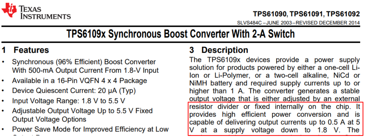
Texas Instrument’s TPS61090
To meet our design requirements, it was clear that a more robust boost converter must be selected. We opted for the MP3422 by Monolithic Power Solutions with a switch current rating up to 6.5A. This converter is rated to supply 2.5A at 5V per the datasheet, compared to the 0.5A rating of the TPS61090.

Monolithic Power Solutions MP3422
One thing that can be deceiving about selecting a boost converter is the switch current rating itself. The maximum switch current is not equal to the load requirement but rather a function of that value, the inductor ripple current, and the converter’s duty cycle. This can be calculated per the MP3422 datasheet using the formula below, where:
ILim(min) = 6.5A
ΔIⳑ = 1.34A (see “Basic Calculation of a Boost Converter's Power Stage” for Equation 2)
D = 0.50 (see “Basic Calculation of a Boost Converter's Power Stage” for Equation 1)
Therefore:
IMAXOUT = (6.5 - (1.34/2))(1-0.5) = 2.92A
This formula tells us that the maximum switch current of the converter actually needs to be higher (~2X higher in this case) than the maximum load requirement (3A) to achieve a consistent 5V out. Since the IMAXOUT is slightly below our max requirement (3A), we may need to raise the output voltage to ~5.25V to compensate for a possible voltage drop at 3A output. Real-world testing will inform us if this is necessary. A boost converter with an even higher switch current may be needed if reliability becomes an issue. It is important to accompany the converter with an equally rated inductor, for which we chose a 2.2uH inductor with a 6.5A saturation current.

With the first iterations of our design, we tried to maximize the performance of the TPS61090 rather than replacing it entirely. We were able to get slightly better performance with an optimized PCB layout and a different charge controller (MP2607), but we ultimately ran into the same voltage drops that the PowerBoost struggles from. We are currently taking the time to revamp the design with the new MP3422 boost converter and an equally powerful charge controller (Texas Instrument’s BQ24070). Next week we will dig into the charge controllers on both the PowerBoost & ChargeBoost to understand the essential features and improvements with the BQ24070, stay tuned!

Adafrruit’s PowerBoost 1000C (MCP73871 + TPS6190). Voltage drops to 3.8 at 1.8A (not ideal).

Kickstart Design’s ChargeBoost 2000 (MP2607 + TPS61090). Voltage drops to 4.07 at 1.8A (slight improvement but not perfect).